
Jas Singh
I'm a passionate Computer Scientist interested in the logical puzzles that come with Game Development.
Resume
GitHub
Projects
This section showcases some of my recent projects.
[Row] A wacky, polished Global BC Game Jam entry. Play it on itch.io!
[AE86] A C++ rigidbody physics engine built from-scratch.
[Gouken] An iOS fighting game whose mechanics are modelled after Street Fighter: Third Strike.
[ShadowDancer] A Thief: the Dark Project (1998) clone with a single level and functioning light and sound detection-based AI..
[Hand-written Multi-Level-Feedback-Queue Scheduler for PintOS] A Stanford Computer Science assignment where I replaced a toy OS' round robin scheduler in favour of a priority-based feedback one instead.
Row - Global BC Game Jam Entry
Play now on itch.io | RepositoryA wacky physics-based game inspired by Bennett Foddy. Made during a weeklong Game Jam. Play it here!
AE86 - A C++ Rigidbody Physics Engine
Repository AE86 is a physics system made for the DKEngine, a video game engine done as course-work in a team of 12 students. I solely led AE86's development, attaining a 98% final grade in the class. Built in C++ with the following reference textbooks:- Game Physics Engine Development by Ian Millington
- Physics for Game Developers by Bryan Bywalec and David M. Bourg
- Real-Time Collision Detection by Christer Ericson
Features
Rigidbody Physics Engine
Code
Introduction
To fully support rigidbody physics, one needs to consider the application of Newton's Laws of Motion in 3D.
The most challenging part of this is Newton's second law, which requires the modeling of torque and,
consequentually, angular acceleration/velocity. To support this, we need to maintain an intertia tensor,
a type of matrix transformation, for each rigidbody. This is dependent on the body's shape and mass distribution and,
in combination with torque, lets us obtain a body's angular acceleration after forces are applied.
Newton-2 for Rotation
Recall that for Newton's second law, one can derive a change in acceleration,
a, from a force applied, f, on a mass, m, with the following formula:
In the case of angular acceleration, we have rotational equivalent concepts to force and mass
called torque, τ, and moments of inertia, I:
We can think of torque as the rotational equivalent of force and the moment of inertia as a measure of how difficult it is
to change the rotation speed of an object. Depending on the axis you care to spin an object about, it may have
different moments of inertia. The moment of inertia depends on the mass of the object and the distance of the mass
from the axis of rotation.
We need to therefore figure out the torque and moment of inertia for a rigidbody after a force is applied.
It turns out we can find torque with the given equation:
Where pf is the location on the rigidbody that a force is applied with respect to its centre of mass,
and f is the amount of force applied in Newtons. One can visualize this as below:

Take the shapes above, where X denotes their centres of mass.
Experience tells us if we're applying a force at a point that goes through the centre of mass,
we have no rotation (as is the case with the example on the left). Otherwise there is a rotation
change by a factor of the location our force is applied to relative to the object's centre of mass
(as is on the right side of the figure). This is, in a nutshell, what we are doing with the above formula to obtain torque.
We can think of torque as the rotational equivalent of force.
At this point, we return to obtaining the angular acceleration
of a rigidbody by multiplying our now-derived torque, τ, with I-1 - the inertia tensor inverse.
Inertia Tensors
We can think of torque as the rotational equivalent of force and moments
of inertia as an object's resistance to torque about a given axis of rotation (acting on torque similarly to how mass acts on force).
Pertaining to game development, the ability to apply torque to different points - and therefore requiring the support of arbitrary
axes-of-rotation - is an important consideration. The fixed nature of a single moment of inertia therefore doesn't suffice to model our rigidbody physics.
To rectify this problem, we look to implementing inertia tensors
- 3×3 matrices that generalize moments of inertia for arbitrary axes-of-rotation -
for every rigidbody. In Physics, we construct a moment of inertia about an axis A with the following formula:
Where n is the number of particles, dpi→a is the distance of particle i from the
axis of rotation a, and Ia is the moment of inertia about that axis. From this, an inertia tensor is
constructed starting with the diagonal axes-of-rotation, as so:
We construct the non-diagonal entries of the matrix with the following formula, denoted as the products of intertia:
However, keeping track of different particles (with their own masses) composing a rigidbody
is very unwieldy for a game, especially where rigidbodies can take any arbitrary shape usually authored by
artists in a modeling program. To solve this, we look to:
- Implementing generalized inertia tensor formulas for uniformly-distributed shapes,
such as cuboids, spheres, or rectangular prisms.
- Provide functionality to dynamically construct an inertia tensor from a passed-in mesh
(code), roughly with
the following algorithm:
- Take all unique vertices of a mesh, treating them as particles of a body that is uniformly-distributed.
- Assume the mesh's centre of mass to be its origin*
- Associate each vertice's location with respect to the object's centre of mass and current axis-of-rotation.
- Fill in the inertia tensor with the formulas defined above now that mass and particle positions are defined.
* NOTE: this unfortunately asks that modelers set the origin of meshes to the centre of the mesh itself. As the project's asset creation phases were relatively short (about the tail-end of the semester), I am unsure of if this places unneeded burdens on the art team and if a better method could be employed.
It is also important to note that this current implementation/algorithm in the AE86 engine leads to some wonky behaviour, with more time an algorithm such as the one in Brian Mirtich's Fast and Accurate Computation of Polyhedral Mass Properties paper would be implemented instead.
With inertia tensors handled, we can look to implementing AE86's time-step function to finally simulate linear and angular responses to forces.
D'Alembert's and Time-Steps
D'Alembert's principle essentially states that if a set of forces or torques are operating on a body at the same time, you can add them all together to get a single, equivalent force/torque. Essentially:This is important as it allows us to update our physics simulation at discrete intervals, with forces applied between updates being gracefully converted into a single aggregate one. This lets other systems, such as the gameplay code, running at different tick-rates than the physics loop, to freely apply forces to rigidbodies.
This leads us to constructing our actual time-step function, which can be seen below (code):
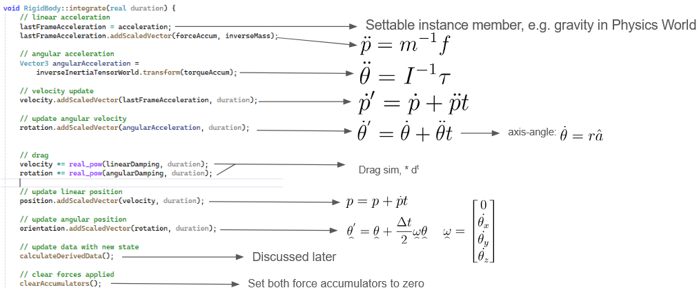
Numerical integrations for linear positions, linear velocities, and angular velocities are fairly straightforward but the formula for an angular positional update is a bit more involved. An explanation for how it is derived can be found here. The engine by default supports an optional damping parameter (set between 0.0 and 1.0) as opposed to an actual simulation of drag forces as for most purposes that is overkill.
CalculateDerivedData (code) is responsible for updating internal data relating to the rigidbody upon position and orientation change. Chiefly: the transformation matrix that brings the rigidbody from body space to world space, and the inertia tensor as it is dependent on the current orientation of the body.
From here, integrate can be called at a specific tick-rate to induce a simulation and so long as forces are being applied to rigidbodies, they will be simulated.
Creating and Syncing the Scene Graph
Code
A scene graph hierarchy, much like the one in Unity, was made for the engine to support the childrening of objects to other objects.
This functions essentially as nested local spaces, with transformation matrices to convert between local "child" space and
world space coordinates. This functionality is important for many use-cases, for example it allows a car's wheels to move
as the car moves and also for the car wheels to rotate without the car rotating itself.
Essentially, each object in the game has an instance of the Transform class, holding its parent and its local orientation and position.
Programmatically, to obtain the transformation matrix from local to global coordinate systems, we recursively climb the tree creating transformations
for each parent
(code)
This way, we construct a matrix transform for an entity (a) with a parent (b) and grandparent (c) to world space like so:
Another issue arises, however, when gameplay code makes changes to an entity's position while physics is
integrating a time-step. Since both systems are multi-threaded, this race-condition is possible and
therefore syncing is required. Moreover, rendering, which is also its own thread, requires position and orientation data
for all entities with meshes. The simplest solution we opted for is locking the entire scene graph before initiating a physics
time-step or rendering all meshes. This works well for our engine, especially since there aren't many gameplay scripts
nor a particularly deep hierarchy in any existing scenes.
One potential point of optimization if given more time would be for
the rendering system to operate on a deep copy of the scene graph.
Rendering, unlike the gameplay or physics systems, is read only - it does not change an entity's transform
data. This means that instead of locking the scene graph, rendering all nodes, then unlocking the graph, we can instead:
lock the scene graph, create a deep copy of it, then unlock it. This could potentially thwart CPU cycles of the gameplay
or physics threads waking up and being slept upon trying to modify the scene graph while rendering is running.
Car Dynamics
Code
Preface
The following texts were used as reference material for implementing car dynamics:
- Car Physics for Games by Marco Monster
- GDC Talk: The Science of Off-Roading: Uncharted 4's 4x4
- Making Custom Car Physics in Unity (for Very Very Valet)
Four Implicit Tires, Three Forces
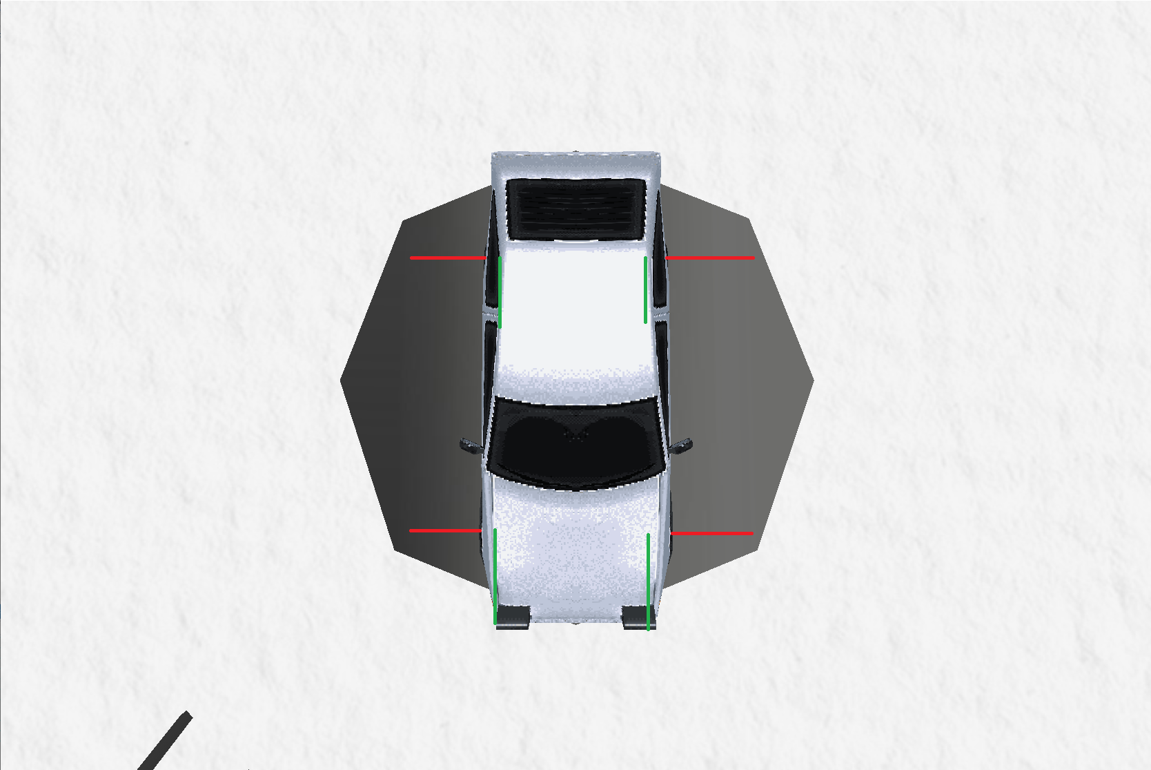
A lot of car dynamic simulations model a car with five rigidbodies: one for the car's body and one for each wheel, with physics joints connecting them together. Others go for an implicit route where there's only one rigid-body for the car's body and four implicit wheels modelled through ray or spherecasts. In AE86 we opted for going the implicit route, calculating three individual forces for each tire:
- Acceleration
- Steering
- Suspension
Acceleration Force
To feel more like you're controlling a car in our engine, we simulate the steady ramp up of acceleration as the pedal is pressed before the car reaches a top speed. To do so, we opt to "simulate" a car engine's torque by implementing a simple look-up curve, similar to real ones engines have like below: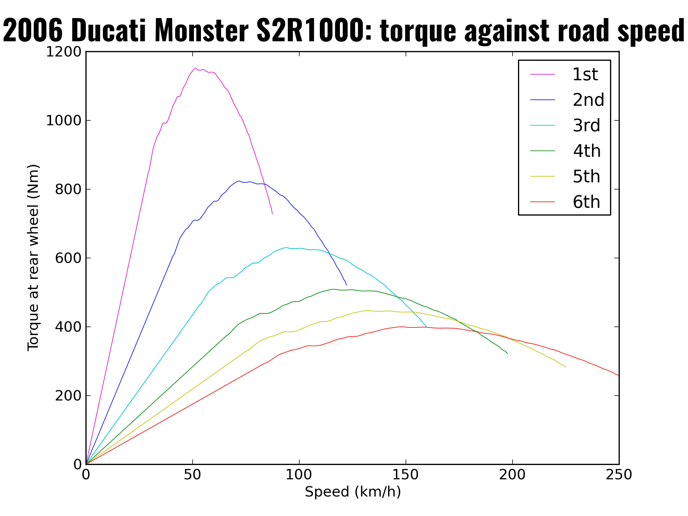
In this curve, we can see that the engine's torque ramps up and drops down as the car reaches top speed (dependent on which gear the car is currently in). In our game, we create a simpler curve (with only a few values to interpolate between) and the top speed is an arbitrary value determined for the car. We also stop applying the engine's torque whenever this top speed is reached, only doing so again once the speed drops.
In essence, for both rear tires (the cars in the engine are RWD) we:
- Obtain the tire's forward direction as a 3D Vector
- Look up how much torque to apply from our curve if the pedal (W key) is pressed, otherwise assume the torque to be zero
- Multiply the torque by the vector obtained in step 1 - this resulting vector is total force the tire will exert
- If we are below top speed, apply the vector from step 3 on the car's rigidbody at the position of the tire
It is important to also note that should we want to implement actual look-up curves from real life vehicles, we would need to add an extra step of simulation: the RPM of the engine converted to an RPM of each rear tire. We would have to simulate the torque of the engine applied on the drive shaft, instead of just the tire, and then calcualte the resulting RPM of the wheels to get a more accurate depiction of the vehicle's speed. To do so, the following formula outlined in Marco Monster's paper linked above would have to be implemented:
Where
u is a unit vector which reflects the car's orientation,
Tengine is the torque of the engine at a given rpm,
xg is the gear ratio,
xd is the differential ratio,
n is the transmission efficiency of the engine and
Rw is the wheel's radius
We however did not have time for this so opted for a simpler curve look-up.
Steering Force
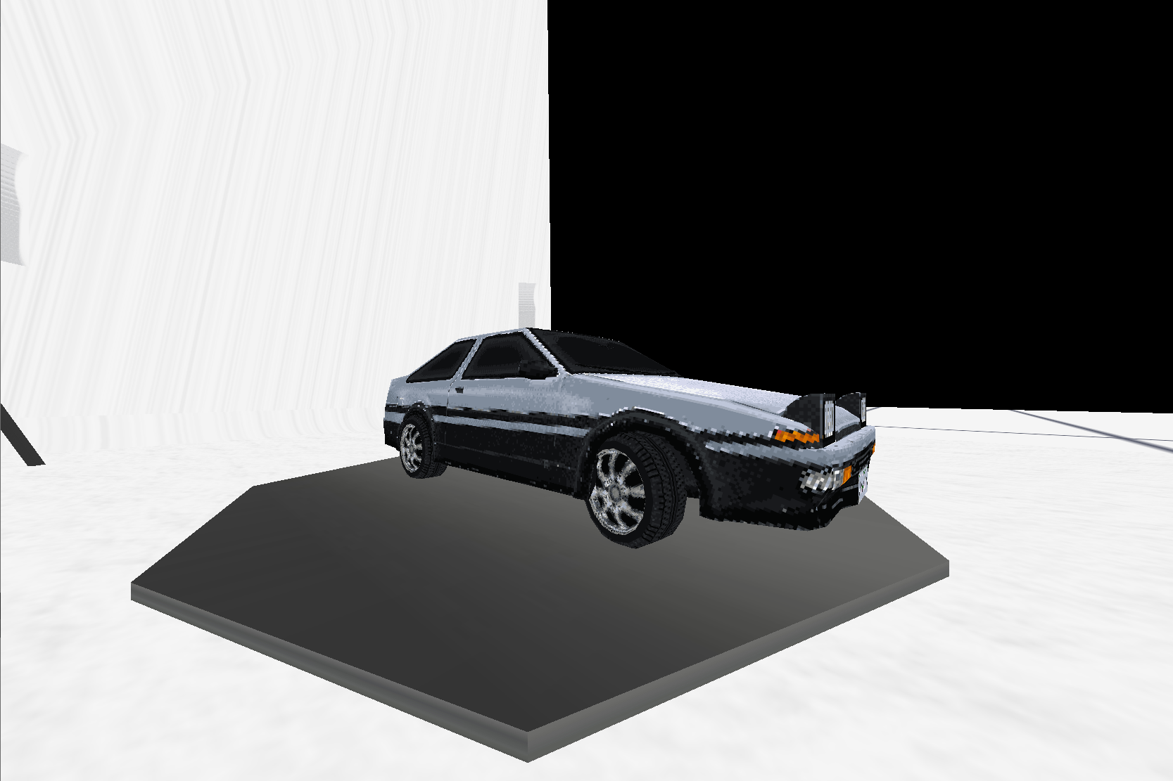
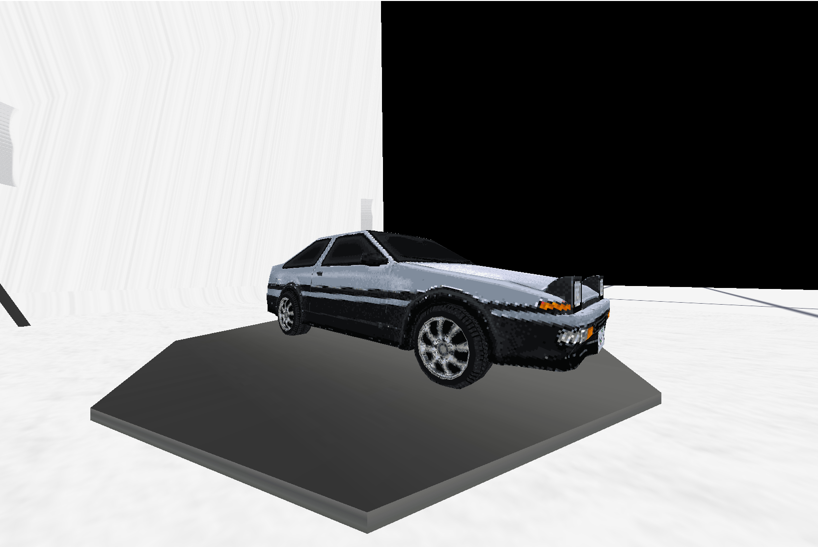
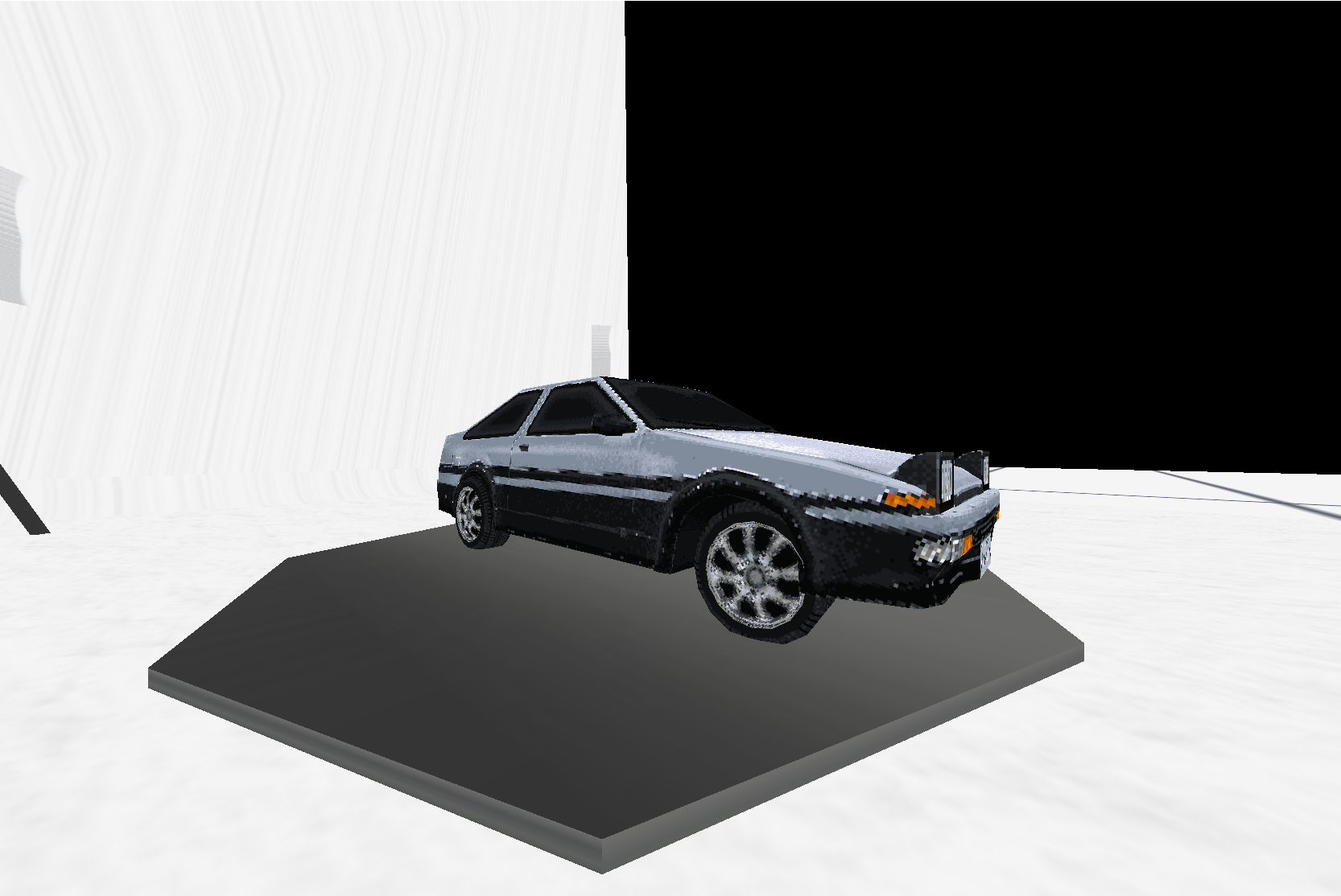
Now that we are able to simulate the acceleration of our vehicle, we need to consider how to turn the car as well. To begin with, we map the car's rotation about the Y axis to the A and D keys. Then, we apply a simple algorithm to determine the lateral force of the car and therefore apply steering. To that effect, we employ the following algorithm on each front tire (full code):
- We grab a normalized vector of the right side of the tire aka the steering direction
glm::vec3 steeringDir = tire->transform->getRight(); - We get the velocity of the tire (aka the velocity at the corner point of the car's rigid body)
AE86::Vector3 tireVel = carRigidBody->getVelocityAtWorldPoint(AE86::Vector3(tireWorldPos.x, tireWorldPos.y, tireWorldPos.z)); - Project the tire's velocity onto the steering direction vector (a simple dot product since its normalized)
float steeringVel = glm::dot(steeringDir, glm::vec3(tireVel.x, tireVel.y, tireVel.z)); - Determine how much we want the velocity to change by, affected by the grip of the tire (a number between 0.0-1.0 that dictates overall traction)
float desiredVelChange = -steeringVel * 1.0f; - Reverse engineer what this entails as a desired change in acceleration
float desiredAcceleration = desiredVelChange / deltaTime; - Compute the final steering force to apply to the vehicle based off the desired acceleration change and mass of the tire (F = MA)
AE86::Vector3 finalLatForce = AE86::Vector3(steeringDir.x, steeringDir.y, steeringDir.z) * tireMass * desiredAcceleration;
Conclusion
With this simple simulation, a car in our engine controls and feels like one. If given more time, suspension would also be implemented to allow for ramps and variable height terrain. Overall, this was a great learning experience and a newfound respect for more complicated driving simulations.Internal Math Library
Code
As apart of the physics engine an internal math library was implemented for learning purposes. It boasts the following features:
[A Vector3 Class]
This class represents a vector in ℝ3 space, it supports addition, dot and cross products,
as well as methods for magnitude and squared magnitude.
[A Quaternion Class]
This class is a normalized quaternion (length of 1) as that is a requirement for a quaternion to be a valid rotation.
It supports quaternion multiplication, addition, as well as conversion into a rotation matrix. A quaternion not only avoids issues
such as gimbal locking (as is prevalent with Euler Angles) but also allows
us to gracefully support angular acceleration and angular velocity with the help of axis-angle vectors, as is required for 3D Rigidbodies.
[4x4 and 3x3 Matrices]
3x3 and 4x4 column-major matrices that support multiplication, addition, transposition, and inverses (where matrices are non-singular).
Under-the-hood, the 4x4 matrices are actually 4x3 matrices where the final row of [0, 0, 0, 1] is implicit in all calculations. This saves storing
four extra doubles. The trade-off for this is the requirement for hard-coded methods for transformations on directions vs points.
Gouken - A Third Strike-Esque Fighting Game
Repository Built for iOS on SceneKit - a Swift framework for Game Development.Features
In fighting games, special moves like Hadoukens and Shoryukens require players to input specific sequences of
motions (like quarter-circles) and button presses. To recognize these moves, the game needs to track the
player's input history. However, naively storing the last few inputs isn't enough because these inputs are
read frame-by-frame.
Input Buffers and Special Inputs
Code
For example, let's expand upon the ramifications of a naive approach to perform the move sequence below:
A player would need to press these inputs in a frame-perfect sequence, meaning each input must be within 16
milliseconds of the next. This level of precision is too difficult for most players.
To make special moves more achievable, Gouken stores a longer history of inputs and processes them with
some leniency. We use a Ring Buffer Data Structure for this purpose. This structure efficiently keeps track
of many past inputs, allowing the game to recognize valid sequences even if the inputs are not perfectly timed.
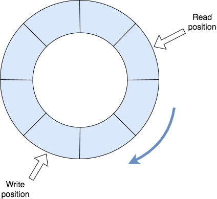
Gouken uses a ring buffer to store the player's last 60 inputs and checks them against the character's
move list. The parsing algorithm in Gouken determines which moves have higher priority and
how leniently to interpret the inputs. For instance, when parsing the last 18 frames of input,
as long as the sequence includes Down, Forward, and Punch in that order, a Dragon Punch will
be triggered, regardless of any other inputs in between.
Below is a code snippet showing how special input parsing is implemented:
for (_, move) in seq {
  let moveSequence = move.sequence
  let frameLeniency = move.frameLeniency
  var currentFrame = 0
  var sequenceIdx = moveSequence.count - 1
  while (currentFrame < frameLeniency) {
    if move.priority < currentMovesPrio {
        break
    }
    let readIdx = (buffer.writeIdx - currentFrame - 1) < 0 ? bufferSize - currentFrame - 1
      : (buffer.writeIdx - currentFrame - 1) % bufferSize

    if (moveSequence[sequenceIdx] == buffer.buffer[readIdx]) {
        sequenceIdx -= 1
    }
    if (sequenceIdx == -1) {
        currentMove = move
        currentMovesPrio = currentMove.priority
        break
    }
    currentFrame += 1
  }
}
Made during a three month long course, we sadly did not have the time to expand much past this. Given more time, we would opt to closely follow
Street Fighter 6's input buffer rules.
Dynamic Hitboxes and Hurtboxes
CodeFighting games need a system to dynamically draw hitboxes and hurtboxes for each move. Each move has its own animations and may include specific invulnerable areas, such as Ryu's Shoryuken. To manage this, we've linked keyframes to each animation. This allows us to enable and disable hitboxes and hurtboxes as needed, matching the behavior shown in the clip below:
The below code-snippet defines the hitboxes for a light punch:
CharacterMove(sequence: [ButtonType.LP], stateChages: CharacterState.Attacking, priority: 1, frameLeniency: 2, attackKeyFrames: [
            AttackKeyFrame(keyTime: 0.1, name: "Hand_R", boxType: BoxType.Hitbox, boxModifier: BoxModifier.Active),
            AttackKeyFrame(keyTime: 0.2, name: "", boxType: BoxType.Hitbox, boxModifier: BoxModifier.Inactive, setAll: true),
            AttackKeyFrame(keyTime: 0.3, name: "Hand_R", boxType: BoxType.Hitbox, boxModifier: BoxModifier.Active),
            AttackKeyFrame(keyTime: 0.4, name: "", boxType: BoxType.Hitbox, boxModifier: BoxModifier.Inactive, setAll: true),
            AttackKeyFrame(keyTime: 0.5, name: "Hand_R", boxType: BoxType.Hitbox, boxModifier: BoxModifier.Active),
            AttackKeyFrame(keyTime: 0.6, name: "", boxType: BoxType.Hitbox, boxModifier: BoxModifier.Inactive, setAll: true)
This system also enables us to balance moves based on their "start-up," "active," and "recovery" times. It allows us to fine-tune each move for better game balance, as shown below:
Collision detection is handled using bitmasks along with SceneKit's physics system. This setup identifies which hitboxes/hurtboxes have collided and determines whether an attack should be triggered. They are defined programmatically like so:
// Hitboxes and Hurtboxes bitmasks.
let p1HitBox = 1 << 0  // Binary: 00000001
let p2HitBox = 1 << 1  // Binary: 00000010
let p1HurtBox = 1 << 2 // Binary: 00000100
let p2HurtBox = 1 << 3 // Binary: 00001000
This allows us to implement hit detection with the following table:
| P1 Hitbox | P1 Hurtbox | P2 Hitbox | P2 Hurtbox | |
|---|---|---|---|---|
| P1 Hitbox | No | No | No | Yes |
| P1 Hurtbox | No | No | Yes | No |
| P2 Hitbox | No | Yes | No | No |
| P2 Hurtbox | Yes | No | No | No |
Where "Yes" means a collision has occurred and "No" otherwise. Successful collision events get queued and processed at the beginning of our game's next update tick.
Characters as State Machines + Combo Routes
Code
In Gouken, we model each character as a Finite State Machine (FSM). This simplifies game logic by limiting the actions
a character can take based on their current state, rather than using complex nested if-else checks to account for every
possible scenario.
For example, when a character is jumping, we only need to check if the player gets hit or completes the jump,
instead of considering every possible situation. Below is a State Transition Diagram and Table for Gouken's character FSM:
| Current State | Next State | |||||||
| Input = Nothing | Input = Left | Input = Down | Input = Right | Input = Up | Input = Attack | Input = Get Hit By Low Attack | Input = Get Hit By Heavy Attack | |
| Idle | Idle | Walking Backward | Crouching | Walking Forward | Jumping | Heavy Attack | Staggered | Staggered |
| Low Attack* | Idle | Walking Backward | Crouching | Walking Forward | Jumping | Low Attacking | Staggered | Staggered |
| Heavy Attack* | Idle | Walking Backward | Crouching | Walking Forward | Jumping | Heavy Attacking | Staggered | Staggered |
| Staggered* | Idle | Idle | Idle | Idle | Idle | Idle | Staggered | Staggered |
| Walking Forward | Idle | Walking Backward | Crouching | Walking Forward | Jumping | Heavy Attack | Staggered | Staggered |
| Walking Backward | Idle | Walking Backward | Crouching | Walking Forward | Jumping | Heavy Attack | Staggered | Standing Block |
| Crouching | Idle | Walking Backward | Crouching | Walking Forward | Jumping | Low Attack | Crouch Block | Staggered |
| Jumping | Jumping | Jumping | Jumping | Jumping | Jumping | Jumping | Staggered | Staggered |
| Crouch Block* | Idle | Walking Backward | Crouching | Walking Forward | Jumping | Low Attack | Crouch Block | Staggered |
| Standing Block* | Idle | Walking Backward | Crouching | Walking Forward | Jumping | Heavy Attack | Staggered | Standing Block |
*States are directly linked to animations, those with asterisks don't take inputs until after so most inputs are processed only after the animations are complete. With the only exception being taking a hit, which cancels you into another state (blocking or staggering).
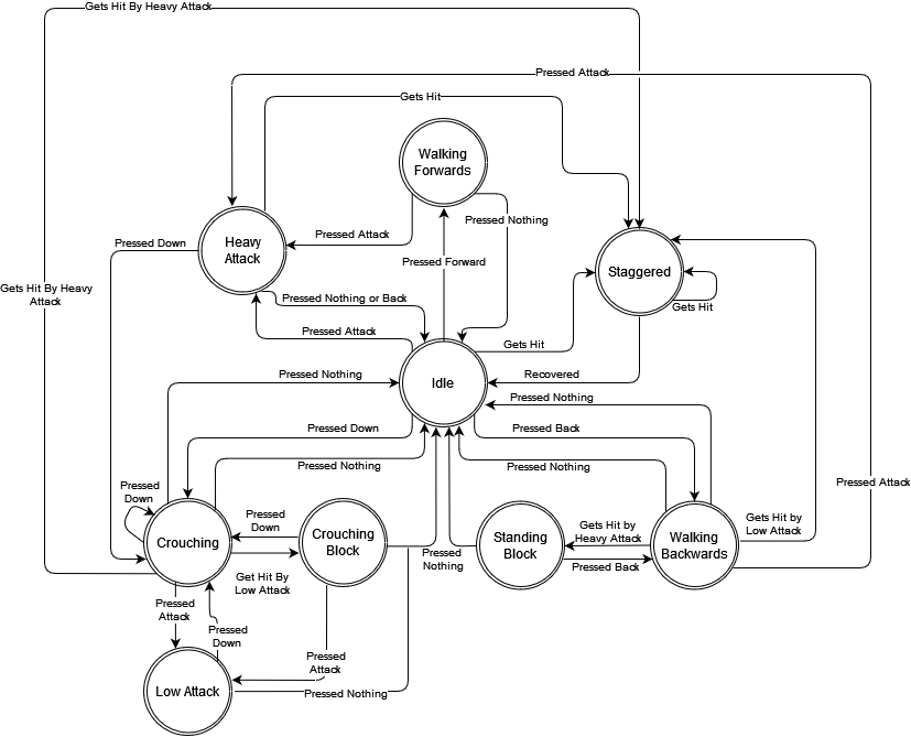
For the attacking, staggered, and blocking states, we can loop the animation of the resulting state-transition depending on the input. For example, a character walking forwards being hit by a low or a heavy will get staggered, however, a heavy will stagger them for longer as depicted below:
This is crucial for fighting games like Gouken because it enables the creation of a combo system by varying the stagger times that different moves apply. Moreover, we can tune how long it takes a blocked attack to fully recover vs a whiffed attack, which opens up design space for balancing purposes. Unfortunately, we ran out of time in the course to fully design functional combo routes. Developing these would require creating animations, fine-tuning them, and expanding the move list. With more time-to-develop, this would be a top priority.
ECS, Update Loop, and Frame-Rate
Loop Code | ECS CodeRegarding flow-of-control, SceneKit provides a rendering/physics loop where you can hook your code changes in using callbacks. Below is a complete diagram of SceneKit's update loop:
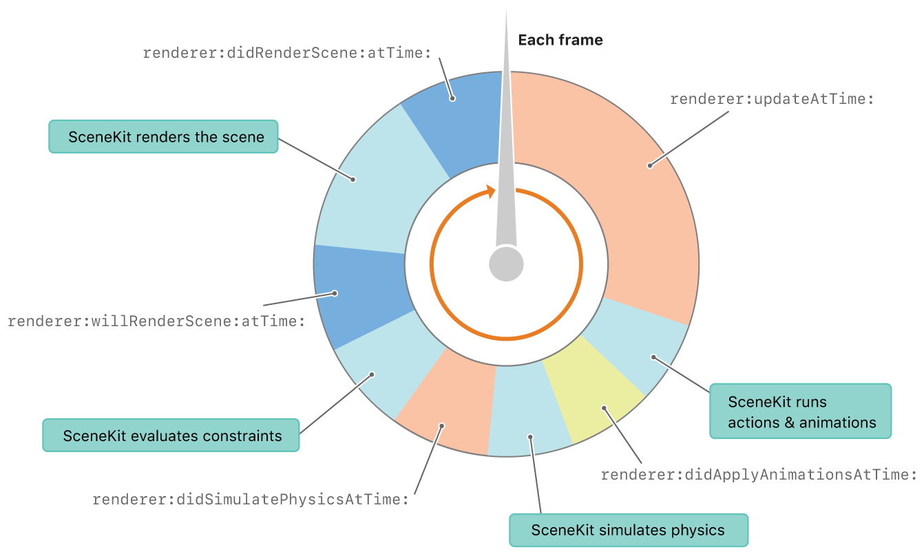
In the above diagram, blocks prepended with "renderer:" are functions we can implement that will be called at that specific time in the game loop.
This allows us to implement per-frame game logic to be executed after or before specific events. For example, one can implement renderer:didSimulatePhysicsAtTime: to handle
collision events right after physics has finished being simulated.
In Gouken, we implement both the renderer:updateAtTime: and renderer:didSimulatePhysicsAtTime: functions.
The former houses all of our core game logic, handling character state transitions, win cons, netcode, etc.
whereas the latter appends collision events to a queue to be processed in future game loop ticks by the renderer:updateAtTime: function.
Moreover, we opted to implement an Entity Component System to better handle the addition of new code. Because of this, a programmer need only create an
entity or new component, and it will be called in the rendering loop automatically. as can be
seen by the following code-snippet:
entityManager.entities.forEach { entity in
  entity.update(deltaTime: deltaTime)
}
Peer-to-Peer NetCode
Code
Two conditions are necessary for a fighting game to have functioning multiplayer: as fast-as-possible latency between players and deterministic gameplay. In order to service the former, a peer-to-peer approach is required (as an additional hop between the clients and a server would be too slow) and a deterministic approach is required so that both players can send eachother merely inputs and handle state transitions accordingly on their own machines. We will expand on both aspects in the below sections.
Peer-to-Peer via iOS' Multi-Peer Framework
iOS's Multi-Peer Connectivity framework enables seamless communication between nearby devices
without requiring an internet connection. Utilizing both Bluetooth and Wi-Fi, it supports
peer-to-peer connectivity for real-time multiplayer experiences. Two devices, on the same wireless network or
within Bluetooth range, can join eachother for a match of Gouken.
As of now, only two users on the same network/within bluetooth range can play together. This is due to the need of a
session key to be exchanged between both clients, of which only one is hard-coded at the moment. Given more time, we would
implement a server browser and lobby system to match-make users.
Deterministic Game State
Thanks to the "Characters as State Machines" and "Input Buffer" implementations, a Gouken match
can be completely reconstructed with just it's input history provided. This means that Gouken's game state is deterministic - i.e. 100% reproducible. The below figure gives a visual example of what a non-deterministic fighting game would play like:
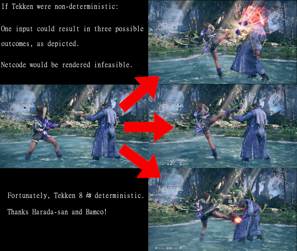
A deterministic fighting game makes netcode much easier to reason with! It allows us to send packets between clients containing only the inputs of each player, plus maybe some metadata to detect disconnections. Each player's machines then
inserts the incoming inputs into their respective input buffers and updates the game state accordingly - advancing to the next frame.
Netcode Steps Going Forward
Sadly, this is as far as we got with Gouken's netcode during the course. We found that it worked well locally on physical iOS machines as well as simulated ones, however, if we weren't playing over LAN or Bluetooth, it's likely the latency would be too slow for the game to run smoothly. If we were to continue working on the title, Delay-Based Netcode would be the first step made towards creating a smoother user experience. However, Rollback Netcode (or GGPO) would be the ultimate standard to achieve.ShadowDancer - a 3D, First Person Stealth Game
Repository Built using the Unity Game Engine over the course of a 4 month semester.Features
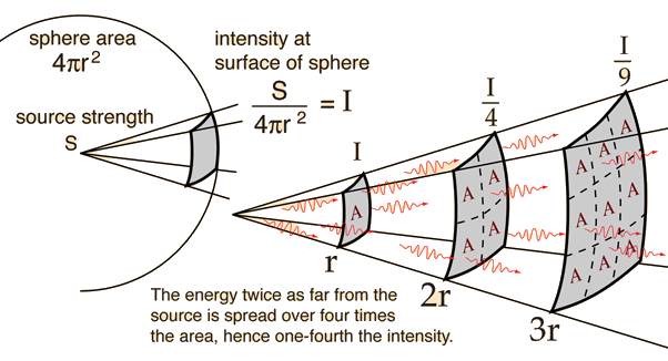
The illumination at a point is inversely proportional to the square of the distance
of the point from the light source and directly proportional to the intensity of the light source.
The unit for measuring illumination, candelas per square metre (cd/m2), is called luminance.
ShadowDancer detects how much noise the player is making and notifies nearby enemies to investigate. This is implemented
by having the enemy AI's update loop check how much noise the player is making and whether or not it is in audible range.
Light Level Detection
In other words, let L be the luminance emitted by a given light source, then the luminance of the player, P, is given by:
Where r is the distance from the player to the light source. This is how ShadowDancer calculates the illumination of the player.
Every light source has a collider which runs a script to update the luminance value of the player with the above formula.
It is then clamped to a value between 0.0 and 1.0 and is factored into a scalar multiplication of all enemy FOVs. When light sources overlap,
ShadowDancer sums the illumination from all sources before clamping. The below figure gives a more visual depiction of how illumination is calculated
in ShadowDancer:
Moreover, the light calculation is dynamic - i.e. a light source can be destroyed and it will no longer factor into determining the player's luminance. See below:
Sound Level Detection
if (IsPlayerInAudableRange() || IsThrownObjectInAudableRange()) {
  if ((soundIntensity >= mediumSoundThreshold) && (soundIntensity < loudSoundThreshold)) {
    LookAroundForPlayer(positionToChase);
  }
  else if (soundIntensity >= loudSoundThreshold) {
    ChaseThePlayer(positionToChase);
  }
}
Additionally, the player can also find throwables on the map and use them to create noise - distracting nearby enemies - as depicted below:
Things that determine how much noise the player makes is the surface they are walking on and the action taken, such as crouch-walking, walking, or sprinting.
We encode these noise levels with values from 1 to 10, where between 1-4 cause enemies to act normally, 5-7 cause enemies to investigate around the
sound-source, and 7-10 cause enemies to barrel towards the source ravenously. Below is a table of the sound values
different floor-tiles cause the player to emit:
Flooring
Sound Emitted (Crouching)
Sound Emitted (Walking)
Sound Emitted (Sprinting)
Grass
2
4
6
Road
4
6
8
Metal
6
10
10
Initial Hurdles
We had encountered performance hurdles with our first naive approach: ray-casting around the sound-source (player or throwable) and checking for enemies within
a certain distance. While, in retrospect, obvious, we soon realized after implementation that this was too compute-heavy as our frame-rate tanked to < 20.
This was a good learning experience overall for our team as we learned that raycasting was not an inexpensive procedure.
Enemy A.I., Alert Levels, and Waypoint System
Code
ShadowDancer has enemies that patrol an area, detect the player through visuals/noise, and chase and attack the player.
To codify these three capabilities, ShadowDancer's A.I. has three "alertness" states that determine their behaviour:
- Patrolling
- Searching
- Chasing
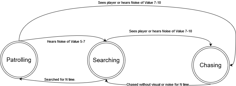
Below, we will expand on the different states, their behaviour, and implementations.
Patrolling
In Patrolling mode, the enemy walks around an area in random locations or follows a set, pre-determined patrol path. To create a patrol path, the level designer places waypoint prefabs on the map (depicted in the above video by Gizmo Spheres) and appends them to an Enemy under a serialized field. The enemy then cycles between the waypoints, waiting at each one for a specified time (determined by another serialized field) before moving onto the next one. Looping back to the beginning when done. If no waypoints are specified, the enemy will randomly pick points on the map to patrol. The below screenshot shows off all of the serialized fields of the EnemyAI component:
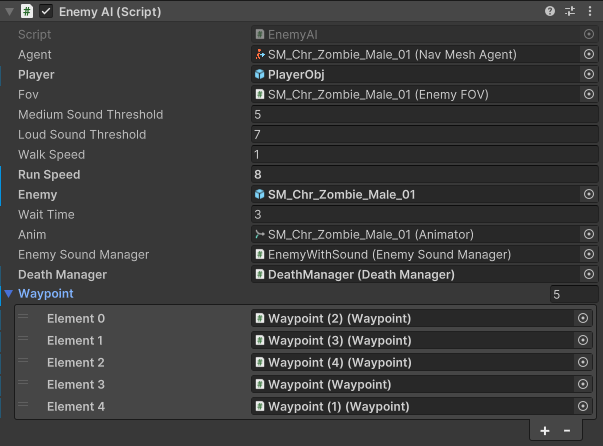
The walk speed determines the patrolling and searching speed of the enemy, the wait time determines how long the enemy will wait at a waypoint before moving onto the next, the run speed determines the chasing speed of the enemy, and the medium and high sound thresholds affect the state transitions from the above diagram, making it so that the zombie can be as perceptive as the designer wants.
Searching
In the Searching mode, the Enemy pathfinds to the last location it saw or heard the player and then meanders around it in a random radius until a specified search time is up. This time is linked to the wait time serialized field in the above image.Chasing
In the Chasing mode, the Enemy runs to the player's location and enters search mode if the player breaks LoS for 5 seconds.Hand-Rolled Multi-Level-Feedback-Queue Scheduler
Repository
Done as part of a class project where we were given a toy Operating System named PintOS (about 300,000 LoC) and were given features to implement, requiring us to read an expansive code-base, understand it, and implement important changes.
Chiefly of which was the thread scheduling, which was a flat Round Robin scheduler with a time quantum of 4 ticks (PintOS by default operated at 100 ticks/second).
Readied Threads were simply dequeued in the order they were enqueued. My job was to extend the functionality of this system to have a feedback scheduler: a dynamic priority-based scheduler where the
more time a thread spends executing - the less priority it has.
PintOS came with two major synchronization primitives - semaphores and locks, which did not
account for priority (as the initial scheduler was priority-less).
The modifications we made were minor but significant:
In order to do so, the following had to be implemented/updated:
Fixed-Point Arithmetic Library
Code
PintOS doesn't natively support floating point numbers. Most compact OS like it don't, The reason being that they would slow the kernel down too much.
This means that real numbers have to be emulated using integers. We look to implementing a Fixed-Point Library to do this.
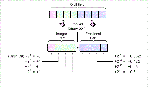
The fundamental idea is to interpret the rightmost bits of an integer as representing a fraction.
For instance, we can designate the lowest 14 bits of a signed 32-bit integer as fractional bits.
This means that an integer x represents the real number
This method is known as 17.14 fixed-point number representation.
In this format, there are 17 bits before the decimal point,
14 bits after it, and one sign bit. A number in 17.14 format can represent a maximum value of:
. Below are the general formulas for working with fixed-point and our C implementation:
Convert
n to fixed point: n * f
Convert
x to integer (rounding toward zero): x / f
Convert
x to integer (rounding to nearest): (x + f / 2) / f if x >= 0,
(x - f / 2) / f if x <= 0.
Add
x and y: x + y
Subtract
y from x: x - y
Add
x and n: x + n * f
Subtract
n from x: x - n * f
Multiply
x by y: ((int64_t) x) * y / f
Multiply
x by n: x * n
Divide
x by y: ((int64_t) x) * f / y
Divide
x by n: x / n
#ifndef __THREAD_FIXED_POINT_H
#define __THREAD_FIXED_POINT_H

typedef int fixed_point;

#define FRACTION 15
#define CONVERT_TO_FIXED_POINT(x) ((fixed_point)(x << FRACTION))
#define CONVERT_TO_INT_TOWARD_ZERO(x) (x >> FRACTION)
#define CONVERT_TO_INT_NEAREST(x) (x >= 0 ? ((x + (1 << (FRACTION - 1))) >> FRACTION)
  : ((x - (1 << (FRACTION - 1))) >> FRACTION))
#define ADD_FIXED_POINT(x,y) (x + y)
#define ADD_INTEGER(x,n) (x + (n << FRACTION))
#define SUB_FIXED_POINT(x,y) (x - y)
#define SUB_INTEGER(x,n) (x - (n << FRACTION))
#define MULTIPLY_FIXED_POINT(x,y) (x * y)
#define MULTIPLY_INTEGER(x,n) ((fixed_point)(((int64_t) x) * n >> FRACTION))
#define DIVIDE_FIXED_POINT(x,y) (x / y)
#define DIVIDE_INTEGER(x,n) ((fixed_point)((((int64_t) x) << FRACTION) / n))

#endif /* thread/fixed_point.h */
Dynamic Priority Calculation
PintOS comes with a basic Round Robin scheduler out of the box. Firstly, this needed reworking to factor in priority.
This meant that the thread struct needed to take in a priority field, like so:
We then modified the queue of ready threads to
be a priority queue, i.e. the highest priority thread gets dequeued to be ran in Round Robin fashion.
struct list_elem sleep_element;
struct list held_lock;
struct lock *curr_lock;
int our_priority;
int nice;
int64_t remaining_time;
fixed_point recent_cpu;
At this point, about half of the work was done. We now had to implement dynamic thread priority using the below formulas.
MLFQS Formulas
Every thread has a nice value between -20 and 20 directly under its control. Each thread also has a priority, between 0 (PRI_MIN) through 63 (PRI_MAX), which is recalculated using the following formula every fourth tick:
recent_cpu measures the amount of CPU time a thread has received "recently." On each timer tick, the running thread's recent_cpu is incremented by 1. Once per second, every thread's recent_cpu is updated this way:
load_avg estimates the average number of threads ready to run over the past minute. It is initialized to 0 at boot and recalculated once per second as follows:
where ready_threads is the number of threads that are either running or ready to run at the time of update (not including the idle thread).
Code Snippets for our C implementation of the MLFQS prioritization
void update_thread (struct thread *t)
{
  enum intr_level old_level = intr_disable ();
  int our_priority = t->our_priority;
  if (list_empty (&t->held_lock))
  {
    t->priority = our_priority;
  }
  else
  {
      int priority = list_entry (list_max (&t->held_lock, compare_locks, NULL), struct lock, elem)->max_p;
      t->priority = our_priority > priority ? our_priority : priority;
  }
  intr_set_level (old_level);
}

void thread_update_recent_cpu(struct thread *t, void *aux UNUSED)
{
  t->recent_cpu = ADD_INTEGER (DIVIDE_INTEGER (MULTIPLY_INTEGER (MULTIPLY_FIXED_POINT
            (load_avg, 2), t->recent_cpu),
            ADD_INTEGER (MULTIPLY_FIXED_POINT (load_avg, 2), 1)), t->nice);
  thread_update_priority_mlfqs (t);
}

void thread_update_priority_mlfqs(struct thread *t)
{
  int new_priority = (int) CONVERT_TO_INT_NEAREST
      (SUB_FIXED_POINT
      (CONVERT_TO_FIXED_POINT ((PRI_MAX - ((t->nice) * 2))),
    DIVIDE_FIXED_POINT (t->recent_cpu, 4)));
  if (new_priority > PRI_MAX)
    new_priority = PRI_MAX;
  else if (new_priority < PRI_MIN)
    new_priority = PRI_MIN;
  t->priority = new_priority;
}
Synchronization Primitive Tuning
Code
Sema V
We modified this operation to unblock the highest priority thread, improving the semaphore mechanism
by using the thread priorities.
This change is essential where multiple threads with different priorities are waiting on a semaphore.
Lock Acquire
Modified to include priority donation to address the issue of priority overturn.
It fixes the problem when a lower-priority thread holds a lock needed by a higher-priority thread.
Lock Release
Modified to calibrate priorities and reverse the effects of priority donation upon
releasing a lock to maintain the correct execution order.
Conditional Variable Wait
Modified to insert threads into the wait list by priority to ensure that the highest-priority thread is awakened first.
This modification is crucial to maintain condition variable usage.

